Frequently Asked Questions
How is Nexcem Made?
Nexcem is the proprietary name for our material. It is a cement bonded wood fiber. We take wood from post-industrial sources such as truss manufacturers and planar shavings from mills. We use only clean un-used softwood lumber that is otherwise sent to the landfill. We do not use post-consumer waste such as pallets or demolition material. The wood is processed and then combined with standard Portland Cement and water to create the Nexcem material, which is used in the manufacture of all our products; Noise Barriers, Retaining Walls, and insulated Wall Forms.
What is the wood treatment process?
What are the dimensions of Nexcem ICF?
We currently have Wall Forms that are 6” (non-load bearing), 8”, 10”, 12” and 14″ wide. All our units are 12″ high and either 24″ or 36″ long depending on the thickness of the block. R values can range between R-8 and R-36. Since there is no thermal bridging with our products, these R-values are true whole wall R-values.
A detailed summary of the different Nexcem insulated concrete form sizes and configurations are available here.
Download the pdf version of our system summary here.
How do we compare to other insulated concrete forms?
This is a big one.
There are so many reasons why Nexcem insulated forms are better than other polystyrene ICFs and we will try to highlight the main advantages below:
Environmental Considerations
Nexcem insulated concrete wall forms contain no polystyrene, foams or plastics. Unlike other ICF systems, there are no VOCs or off gassing with Nexcem. Styrofoam and EPS systems are all petroleum based products. Nexcem is not a petroleum based product and therefore has less of an overall environmental impact. Using Nexcem is also an example of reducing the overall demand for oil and oil derivatives. Nexcem is comprised of simple ingredients; cement and wood aggregate. Nothing in the Nexcem process is remotely hazardous or detrimental to the environment.
Energy input for both cement and Styrofoam products are comparable
100% recycled wood content; We only use recycled waste wood (100% clean, natural softwood lumber) that is taken from sources such as truss manufacturing operations, and otherwise being sent to landfill sites.
Performance Considerations
Nexcem does not burn or melt. This is not the case with Styrofoam and other ICF products. The smallest Nexcem wall has a 4 hour fire rating, zero flame spread, smoke spread of 11 and no black smoke or toxic fumes created in the event of a fire.
Nexcem is more energy efficient. The insulating thermal mass/dynamic effects are better with Nexcem than other ICF systems because with Nexcem, the insulation is placed primarily on the exterior of the concrete mass. Polystyrene ICF foam blocks put 50% of the total insulation on the interior, which actually prevents the transfer of heat/energy between the concrete mass and the interior conditioned space. With Nexcem, all insulation inserts are positioned towards the exterior, where it should be, to maximize any thermal mass gains.
Nexcem is more impact resistant. Both stucco and drywall, when attached to Nexcem result in a solid, durable, impact resistant finish. Polystyrene ICF substrates result in stucco and drywall finishes that can easily be damaged through regular use.
Nexcem is more resistant to termites. We have completed a 7 year termite study with US Forest Service and found no damage to the Nexcem material over this period of time. Although Styrofoam does not provide a food source to termites, it does provide a protected high humidity environment that can also serve as a pathway for termites. It has been found that termites readily chew through the Styrofoam. This does not happen with Nexcem.
Nexcem facilitates improved indoor air quality. The Nexcem material is a hygroscopic material – which means that it has a very large capacity to store and release moisture as required, depending on the environmental conditions. This storage capacity refers to storing moisture in the form of water vapor and increased material moisture content – not liquid water. Also, the Nexcem material and wall system is extremely vapor permeable. It does not act as a vapor barrier, but acts as a vapor regulator and keeps indoor RH (Relative Humidity) levels at a healthy and comfortable level. We have conducted full scale wall tests and have proven that Nexcem does not allow condensation within the wall cavity when used without a vapor barrier, and maintains RH levels below RH 65-70 naturally.
Nexcem promotes healthy indoor environment and inhibits mold growth. Firstly, because the material is hygroscopic and vapor permeable, RH levels are kept low enough such that it is not possible to reach the level of RH where mold can start to grow (typically 70% RH). Combined with the high pH (alkaline) environment resulting from the cement content, this means that the wall system actually helps to inhibit mold growth. Something that doesn’t happen with the other systems. Click below for information on Nexcem and healthy housing.
The composition of Nexcem is all natural and benign materials – unlike polystyrenes. While there is less concern about the health effects of EPS itself, the brominated fire retardants used in most EPS foam (decaBDE or hexabromocyclododecane are the most commonly used) generate health and environmental risks that are generating even more significant concern. The following links show some current research that is available on this topic.
Hexabromocyclododecane (HBCD) information
Brominated Fire Retardants – Janssen
Blum Presentation
Construction Considerations
Our insulated concrete forms are much stronger, and can withstand higher concrete pressures. We have zero blow-outs in the field when poured in accordance with our recommendations.
The blocks require less bracing than the foam ICFs and Nexcem walls don’t bow and bend as easily as the foam blocks. Also, since the blocks are uniform, it is possible to drywall or attach screws to any point on the finished surface, not just at the discrete plastic web locations that are difficult to find with traditional ICF materials.
Because the Nexcem is a free draining material, it is possible to use a high-slump concrete (7” – 9” slump) without adversely affecting your concrete strength. When pouring a very wet concrete mix, the Nexcem material immediately starts to drain the moisture so that it does not result in weaker concrete, while ensuring that there are no voids and making the pouring process easy.
What is the R value of the Nexcem insulated concrete forms?
Our typical units range in R-value, between R-8 and R-28. The Nexcem material has an R-value of 2.00 per inch. This means that all Wall Forms regardless of thickness have a basic R-value of R-8.2. We increase the R-value of the 10″, 12″ and 14″ units by incorporating additional insulation inserts into the Wall Form at the time of manufacture. The inserts are made from mineral fiber insulation (Rockwool) and are also completely fire-resistant and made from recycled content. The inserts are placed inside the Wall Form cavity but positioned towards the exterior to maximize the Thermal Mass effects of the wall system.
We can incorporate non-standard insulation (ex. poly-isocyanurate) in our units for custom orders to achieve up to R-40.
The Wall System Summary and the Technical Guide provide the steady-state two dimensional R-values for our wall systems. The Thermal Performance document provides information on thermal mass and dynamic effects.
What is the true thermal performance of our insulated concrete forms?
This is another big one.
The following explanation on our thermal performance can be downloaded in pdf format with figures here
The standard Nexcem Wall System comprises insulated concrete forms that are filled with concrete. This creates a strong, interconnected structural layer of reinforced concrete. Nexcem building systems provide many advantages; a highly breathable and moisture regulating wall, a 50-year track record of moisture-, fire- and insect-proof materials, high-recycled content, no off-gassing, etc. Another advantage of Nexcem is its thermal performance, which is a result of two properties:
-Lack of thermal bridging; and
-Presence of thermal mass effects
These two characteristics combine to create a wall system with excellent control of heat loss and heat gains. North American housing has been dominated by wood framed systems since World War 2. As the need to improve thermal Performance became more widely recognized, thermal insulation was added to the building enclosure. Codes, standards, and testing procedures were subsequently developed to ensure minimum thermal performance. Thermal performance Requirements and testing became biased toward lightweight framed systems, and rational means of assessing alternative systems were not widely adopted because of the limited number of such systems available. The R-value method of assessing thermal performance had value when proposed not because it was absolutely correct, but because it provided a means to compare otherwise similar wood framed wall systems.
This situation is rapidly changing as the building industry seeks new and innovative ways of building, ways that are truly energy and resource efficient, economical and durable. Many different types of building systems are now being used throughout North America, requiring the development of more realistic means of assessing their true thermal performance.
Although the Nexcem Wall Form System is not a new system, its thermal performance cannot be fairly assessed by the simple methods of the past. This report will present a more realistic assessment of the thermal performance of the Nexcem Wall Form System by accounting for thermal bridging (i.e., 2-D effects) and thermal mass. These benefits will then be discussed in the context of the most modern energy code available, ASHRAE’s proposed revision to Standard 90.1.
Thermal Bridging and Nexcem Insulated Wall Forms
Nexcem and framed wall systems are not simple one-dimensional assemblies. Real buildings are three-dimensional, with corners, window openings, etc. However, most wall R-value calculation methods, and almost all marketing brochures, do not factor in the effects of framing at windows, doors, corners, etc. Thus they tend to over-estimate the true thermal performance.
There has been a lot of research into this and one of the better analyses conducted was by Oak Ridge National Labs over 20 years ago. The researchers concluded that the true R-value of all framed systems was substantially lower than that commonly quoted. For example, they found that a wall system with 2×6 studs at 24” on center and R19 batts had a true “whole wall” R-value of 13.7. This reduction reflects the fact that stud walls are typically 75% insulated cavity, 21% studs, plates, and sills, and 4% headers. Steel stud walls fared even worse, since the metal is so conductive it easily short-circuits the insulation. A metal stud wall with 3-1/2” deep studs filled with R11 batts was found to have a real R-value of only 7.1. The construction details that increase heat flow through a framed wall system have little or no influence on the heat flow through the Nexcem Insulated Wall Form System. Nexcem Wall Forms are designed to ensure that the R-value through the core of the wall is almost the same as that through the web. This not only avoids short-circuiting,it ensures uniform wall temperatures with no cold spots to encourage condensation, create discomfort, or cause dust marking.
Steady-State Thermal Resistance of the Nexcem Insulated Wall Forms
Several combinations of insulated Nexcem Wall Forms and a standard 2×6 wood framed wall were analyzed using the widely recognized and accepted FRAME two-dimensional steady-state finite volume heat transfer computer program. The standard ASHRAE values for conductivity were used for all materials except Nexcem. The Nexcem conductivity value was based on test reports from a national laboratory per ASTM standards. It should be noted that the analyses below are based on “clear wall” samples. As discussed above, corners, partition wall intersections, floor joists, and windows greatly increase the number of thermal bridges in standard 2×6 construction, but not with the Nexcem Insulated Wall Form System.
The results of the analysis are presented in tabular format, with the nominal U- (overall transmittance) and overall R-values, followed by the same values through the middle of the core or stud space, and through the web or wall framing. The final column is the total (i.e., actual clear wall) value.
—————————————————————————
12″ Nexcem Wall Form with 3” insert, plastered inside and out
Data File Name: WF30-76A.F40 (CSA) (WALL JUNCTION)
Title………: WF30 W/3.0 INSULATION
RUN Status….: Standard (Completed)
Nominal Middle Web Total Units
U-Value 0.0485 0.0529 0.0512 0.0526 BTU/hr·ft2·oF
R-Value 20.61 18.90 19.53 19.01 hr·ft2·oF/BTU
Comments: There is almost no difference in R-value between the web and the center of the unit in these highly insulated Wall Forms. As a result, the temperature across the inside face does not vary by more than 0.2 degree Fahrenheit under design conditions.
—————————————————————————
Standard 2×6 (D.Fir-L) wood framing at 16” o.c. with 1/2” OSB, stucco outside and drywall on the inside
Data File Name: 2X6-STUC.F40 (CSA) (WALL JUNCTION)
Title………: 2X6 W/WAFERBOARD AND STUCCO
RUN Status….: Standard (Completed)
Nominal Middle 2×6 Total Units
U-Value 0.0476 0.0520 0.0918 0.0558 BTU/hr·ft2·oF
R-Value 21.00 19.23 10.89 17.92 hr·ft2·oF/BTU
Comments: There is a large difference between the R-value through the framing and the middle of the batt. This causes a relatively large temperature difference of 2.5 degrees F across the interior face. The coldest temperature is 64.8 degrees Fahrenheit, 2.3 degrees colder than the coldest spot on the Wall Form with a 3” insert.
—————————————————————————
Nexcem WF25 Wall Form with 1.5” insert, plastered inside and out
Data File Name: WF25-38A.F40 (CSA) (WALL JUNCTION)
Title………: WF25 W/1.5″ INSERT
RUN Status….: Standard (Completed)
Nominal Middle Web Total Units
U-Value 0.0696 0.0728 0.0701 0.0724 BTU/hr·ft2·oF
R-Value 14.37 13.74 14.27 13.81 hr·ft2·oF/BTU
Comments: The performance of the 10″ Wall Form is similar to the 12″ in terms of uniform surface temperature, amount of thermal mass, etc., but the total heat flow is higher because less supplemental insulation is provided. The coldest surface temperature for the WF25-5 insulated form is 66.5 degrees Fahrenheit, considerably higher than the 2×6 wall system.
—————————————————————————
12″ Nexcem Wall Form with no additional insulation, plastered inside and out
Data File Name: WF30-0A.F40 (CSA) (WALL JUNCTION)
Title………: WF30 BLOCK NO INSERTS
RUN Status….: Standard (Completed)
Nominal Middle Web Total Units
U-Value 0.1124 0.1101 0.1062 0.1095 BTU/hr·ft2·oF
R-Value 8.90 9.08 9.42 9.13 hr·ft2·oF/BTU
Comments: Even with no additional insulation, the Nexcem Wall Form provides uniform interior wall temperatures. The 8” concrete core provides a significant amount of thermal storage mass, and the capacity to resist very high structural loads.
Nexcem Wall Forms and Mass Effect
Materials like concrete, brick, and Nexcem have a high heat capacity, that is, they can store a significant amount of heat or “cool”. This material characteristic has long been known and was taken advantage of by ancient builders of adobe walls, sod roofs, and brick buildings. After many years of neglect, the benefits of thermal mass, as the ability to store heat is called, are being rediscovered by mainstream builders and accepted by building codes, spurred on by studies of passive solar heating, passive cooling, and low-energy houses. The improved thermal performance provided by thermal mass is called the mass effect.
Constructing walls, floors and fireplaces of high heat capacity materials results in a building with an abundance of thermal mass. The thermal mass absorbs and stores heat when the indoor air is higher and releases heat when the indoor air is cooler. This temperature moderating effect improves comfort, and can also greatly reduce space conditioning energy consumption.
In the winter all modern buildings with double-glazed south-facing windows collect more solar energy when the sun is shining than they lose through the windows at other times. The more insulated the window (e.g., low-E and argon filled, triple-glazed), the more “free” energy is collected. However, if the energy that is collected during sunny hours cannot be stored for use during nights and overcast days, it is often lost to overheating of the house and ventilation. Thermal mass allows the free solar energy to be used by providing the energy storage required to level the peaks (sunny days) and valleys (cold nights).
Thermal mass plays as much of a role as the use of quality windows in reducing heating energy consumption, yet it often costs less to provide this mass. Other benefits of thermal mass include the increased ability to survive heating system failures without discomfort or damage, and the ability to use smaller heating systems.
The benefits of thermal mass are even more important in cooling climates and in heating climates during the summer. In most locations, the night-time air temperature is considerably lower than the day-time air temperature. This difference in air temperature can be taken advantage of by encouraging ventilating during the night, thereby cooling the thermal mass. As the temperature rises during the following day, the interior will remain cool. Although this use of thermal mass was widely employed thousands of years ago by, for example, the Anasazi Indians of Arizona, thermal mass is still a relevant and highly successful means of providing a comfortable interior environment with no supplemental air conditioning. Even in hot climates with warm evenings, major benefits can be had from a substantial downsizing in equipment and the shift of maximum cooling to the evening hours, when air conditioning equipment is more efficient and power can be less expensive.
Thermal mass also acts to reduce the need for cooling by absorbing and storing solar energy that falls on walls. The thermal lag of a Nexcem wall is at least 8 hours, meaning that the maximum temperature on the inside occurs 8 hours after the maximum on the outside.
Nexcem and Energy Codes – ASHRAE 90.1
The BSR/ASHRAE/IESNA Standard 90.1-1989R, has been widely used by individual states to govern the insulation levels of buildings other than single family dwellings. This standard is presently being revised and has reached the 2nd Public Review Draft – December 1997 stage. The new version is expected to be formally adopted sometime in 1998. The proposed standard provides large benefits for buildings with thermally massive walls and systems with little thermal bridging. The size of these benefits was based on the results of thousands of detailed energy simulations for many locations and wall assemblies throughout North America.
A thermally massive wall with a much lower steady-state R-value (the value normally quoted) is considered the
equivalent of a lightweight framed wall by ASHRAE. Conversely, using a Nexcem Wall Form with the same or
slightly less than the R-value typically quoted for a framed wall will result in significant space heating energy
savings and improved comfort.
The tables below provides some summary examples of the standard’s requirements for residential buildings
(whose requirements are more stringent than commercial buildings). The R-values are overall minimum R-values including the surface films for Nexcem, and the minimum installed R-value for framed systems. The climate
regions are defined by the number of heating degree days (HDD65) and cooling degree days (CDD50). The data
for some representative cities are shown below.
City | HDD | CDD | Heat/Mix/Cool |
Anchorage | 10570 | 688 | H |
Atlanta | 2991 | 5038 | M |
Charlotte | 3341 | 4704 | M |
Lexington | 4783 | 3754 | M |
Miami | 200 | 9474 | C |
Ottawa | 8571 | 2045 | H |
Phoenix | 1350 | 8425 | C |
Pittsburgh | 5968 | 2836 | H |
Sioux City | 6893 | 3149 | H |
Toronto | 7306 | 2370 | H |
A 2×6 wood framed wall with a drywall interior finish and stucco exterior finish was shown earlier to have a calculated “clear wall” R-value of 17.9, but when the extra thermal bridging inherent in framing around doors and windows is accounted for, ASHRAE considers such a wall to have an R-value of 14.3. This value is still higher than that calculated by the Oak Ridge researchers (they estimate closer to R 12). Such a 2×6 wall system does not meet the requirements of the ASHRAE standard for residential buildings (U<0.067, R>14.9) in colder regions (7201-9000 HDD). The Nexcem 10″ with 1.5” of insulation (R13.8) easily complies for even colder regions (9001-10800 HDD) because of the substantial thermal mass benefits. Even the steady-state, no mass effect R-value of the same 10″ Wall form with 2” of insulation (R15.4) exceeds the requirements for these regions.
ASHRAE R-Value Requirements for Different Wall Systems in Heating Climates
Climate (HDD65/CDD50) | Nexcem Wall | Wood Framing | Steel Framing |
3601-5400 / < 1800e | R8.1 | R13 | R13+3.8is |
5401-7200 / < 1800 | R11.1 | R13 | R13+7.5is |
5401-7200 / 1801-3600 | R11.1 | R13+3.8is | R13+7.5is |
7201-9000 / <1800 | R11.1 | R13+3.8is | R13+7.5is |
7201-9000 / 1801-3600 | R11.1 | R13+7.5is | R13+7.5is |
9001-10800 / < 1801 | R12.5 | R13+7.5is | R13+7.5is |
Note: “is” denotes that the R-value must be provided by a continuous blanket of insulating sheathing.
Typical Heating Climate Minimum R-value Requirements of Proposed ASHRAE 90.1 for Residential Buildings.
For warmer climates, i.e., those with mostly cooling requirements, similar benefits accrue. All of the Nexcem Wall Forms easily provide sufficient insulation in these locations, even in locations with more than 12000
ASHRAE R-Value Requirements for Different Wall Systems in Cooling Climates
Climate (HDD65/CDD50) | Nexcem Wall | Wood Framing | Steel Stud |
< 1800 / < 5400 | R 6.6 | R 13 | R 13 |
< 1800 / < 9000 | R 6.6 | R 13 | R13 |
< 900 / > 9000 | R 6.6 | R 13 | R 13 + R 3.8 is |
Note: “is” denotes that the R-value must be provided by a continuous blanket of insulating sheathing.
Typical Cooling Climate Minimum R-value Requirements of Proposed ASHRAE 90.1 for Residential Buildings
In mixed climates (i.e., those that require some cooling and some heating), Nexcem wall systems can provide sufficient insulation, whereas all steel framing systems require some exterior insulating sheathing to meet the requirements of ASHRAE 90-R1.
ASHRAE R-Value Requirements for Different Wall Systems in Mixed Climates
Climate (HDD65/CDD50) | Nexcem | Wood Framing | Steel Stud |
3601-5400 / < 1800 | R 8.1 | R 13 | R 13 + R 3.8 is |
5401-7200 / < 1800 | R 11.1 | R 13 | R13 + R7.5 is |
5401-7200 / 1800-3600 | R 11.1 | R 13 | R 13 + R7.5 is |
7201-9000 / < 1800 | R 11.1 | R 13 + R 3.8is | R 13 + R7.5 is |
7201-9000 < 1801-3600 | R 11.1 | R 13 + R7.5 is | R 13 + R7.5 is |
9001-10800 / < 1800 | R 12.5 | R 13 + R7.5 is | R 13 + R7.5 is |
Climate (HDD65/CDD50) | Nexcem | Wood Framing | Steel Stud |
1801-2700 / 3601-5400 | R 6.6 | R 13 | R 0 + R 7.5 is |
2701-3600 / 3601-7200 | R 8.1 | R 13 | R13 + R 3.8 is |
3601-5400 / 3601-5400 | R 9.6 | R 13 | R 13 + R7.5 is |
5401-7200 / 1801-5400 | R 11.1 | R 13 + R 3.8is | R 13 + R7.5 is |
Note: “is” denotes that the R-value must be provided by a continuous blanket of insulating sheathing. Typical Mixed Climate Minimum R-value Requirements of Proposed ASHRAE 90.1 for Residential BuildingsWhile this assessment of ASHRAE 90.1 is only cursory and the standard has not yet received final approval, it should be clear that codes and standards are beginning to recognize the substantial benefits provided by the thermal mass and continuous insulation of Nexcem Wall Systems. The ASHRAE standard also provides for the option of elevated levels of insulation for increased energy savings: these more demanding performance targets are termed the Tier II requirements. Tier II levels may be prescribed as minimum values for some energy-saving incentive programs by utilities and government programs. The Nexcem 10″ WF with 2” of insulation can meet Tier II requirements for all building types in climates with HDD < 12600 and any value of CDD. Nexcem Inc. will assist designers, builders, owners, and code officials in calculating the actual required R-value for any performance target, whether ASHRAE 90.1, or other codes. Whole building analysis can be conducted for larger projects to assess the impact of orientation, window type, size, and distribution, internal heat generation, etc.
How does Nexcem contribute to healthy homes and better indoor air quality?
You can download this full document in pdf format here
Indoor air quality is an important issue from both a social and economic point of view. There are several design strategies that can be used to deliver good IAQ. Controlled ventilation, proper design, and the use of appropriate healthy building materials can provide good indoor air quality if used in as part of a holistic design approach. As part of a complete IAQ design strategy, so-called breathing walls can moderate indoor humidity and practically eliminate the potential for fungal growth on building surfaces.
This FAQ reviews the three basic design strategies for IAQ, and the role of breathing walls. The physics of breathing walls are discussed, and the ways in which such walls can improve IAQ are outlined. A research program directed at exploring the properties of low-density cement-bonded wood fibre (Nexcem) is described. The research included material tests, field monitoring of full-scale walls, and computer modelling. Some results of this research are presented and discussed.
Supported by calculations and field data, it is concluded that IAQ can be greatly improved by using a holistic approach to building design. Breathing walls made of vapour permeable and highly hygroscopic materials, such as Nexcem and strawbales, can enhance IAQ when used in conjunction with other strategies.
Introduction
In industrialized countries most people spend more than 90% of their lives inside buildings. During this time the nature of the enclosed environment directly affects the health, quality of life, and productivity of the occupants.
Modern buildings, however, clearly have a problem providing a healthy or even appropriate indoor environment. The US Environmental Protection Agency (EPA) concedes that about 30% of new or renovated buildings have serious indoor air quality problems (IAQ), and ranks IAQ as our most prominent environmental problem (Roodman and Lenssen, 1995). In fact, recent estimates place the direct health care costs of poor IAQ in the US at $30 billion, with sick leave and productivity losses adding another almost $100 billion annually (Fisk and Rosenfeld, 1997).
Extensive measurements by numerous agencies have shown that the typical modern home contains a chemical soup of volatile organic compounds (VOCs) like formaldehyde, xylene, isobutylaldehyde, vinyl chloride monomer, and other organochlorides, aldehydes and phenols from all kinds of manufactured wood products, paints, carpets, and synthetic textiles including furniture and carpets, plastics, foam, tile and carpet glue, etc.
Radon from the soil, ozone from some electrical appliances, and micron-sized particles from many sources add to the health risk. The EPA and Surgeon General estimate between 5000 and 20 000 deaths per year can be attributed to radon gas in the US, where it is the second leading cause of lung cancer (Marinelli and Bierman-Lyle 1995).
Airborne particulates, especially those less than about ten microns in diameter, can seriously damage the lung. Small particles can penetrate deeper into the lung, while larger particles are filtered out by the body’s natural defences.
A major concern in many cold-climate countries is the growing number of studies that link allergies, immuno-depression, and illness to the amount and type of fungal growth in a building (e.g., see Health and Welfare Canada 1987, Scanada 1995). By avoiding surface relative humidity in excess of about 80% RH fungal spores, unavoidable in all buildings, will be starved of the moisture they need to survive. Mould growth within the building envelope can also affect health if an interior air barrier is not present.
Design Strategies for Indoor Air Quality
Several basic strategies can be employed in the design, construction, and operation of buildings to dramatically reduce the presence and concentrations of indoor air pollutants.
Avoidance
The first line of attack should always be the avoidance of products that contain solvents, glues and plastics. There is an increasing number of commercial sources of natural paints, glues, materials, and systems that can be economically substituted for the most dangerous building materials, e.g., particle board, waferboard, carpet, foams, paint (Pearson 1994, Baggs 1996). The use of natural (and unpainted) lime-cement plasters and solid wood as wall finishes, and concrete, linoleum, solid wood, and ceramic tiles for floor finishes can reduce total VOC concentrations by an order of magnitude. Occupants and maintenance staff must also avoid the use of materials and products that might affect IAQ.
Avoiding fungal growth can be difficult if the surface humidity is over about 80%; the paper facing of drywall is an ideal mould growing substrate, and even ceramic tiles will allow mould growth if soap and skin residue remain on their surface. Maintaining a high, and uniform, wall temperature will ensure that the surface relative humidity remains only slightly above the interior humidity. Thermal bridging at framing members, especially steel studs, can result in dramatically lower surface temperatures and much higher surface humidity. Moderating variations in indoor relative humidity through the liberal use of hygroscopic and “breathable” materials can virtually eliminate the potential for fungal growth. A complementary approach is the use of finishes which do not provide food for fungi and/or have a high pH; virtually no fungi can survive on surfaces with a pH over about 10.
Removal
The second step in improving IAQ is pollutant removal. A building should be designed to remove pollutants down to at least the level of the outdoor air, if not lower. This involves increased volumes of, and more controllable, ventilation, porous adsorbers, and plants. Hygroscopic materials moderate RH and can permanently adsorb some VOCs. Plants such as Devilís Claw and spider plants measurably improve IAQ by filtering and humidifying the air while consuming CO2. Any falling or running water will act as a powerful particulate filter by trapping particles.
Studies have shown that 75% of all damaging airborne particulates originate in the exterior air (Turpin, 1997). The proportion is likely higher in healthy homes, which should produce fewer particulates. A combination of an airtight building enclosure and high quality filtration of ventilation air, by mechanical or natural means, can be used to greatly reduce the number of particulates.
Exclusion
Exclusion is the third principle of good IAQ design. Radon control, for example, requires an airtight floor and/or basement system. Exclusion of radon from the interior environment must be a serious design consideration because of the serious consequences of exposure. Ventilation of living areas (i.e., removal) does aid radon control, but it is imperative to first design and build the ground floor or basement as airtight as possible to avoid penetration into the building.
Exclusion of outdoor particulates requires an airtight above-grade building envelope. If the air barrier system is applied to the interior side it can control off-gasing, particulates, and mould spores from within the enclosure system.
The Systems Approach
None of these principles can provide indoor air quality on their own: a holistic approach is necessary. Avoiding materials which offgas is a useful and necessary approach, but ventilation, air barriers, humidity control, and high surface temperatures working together can provide much better IAQ than either approach used independently.
” Atmungsfaehig” or Breathable Walls
” Breathing” walls are often recommended by designers of healthy housing, especially by those who study and practice Baubiologie, but the term itself is used in an imprecise manner in the English language. A review of the lay literature shows that there is considerable confusion about what constitutes a “breathing” wall, and how they work to improve IAQ.
Although “breathing” implies airflow, this is not necessarily the case. In much of the scientific literature, the term simply means that a material or assembly is both open to vapour diffusion and hygroscopic. In essence, this combination of properties allows a significant amount of water vapour (and other gases) to be adsorbed and released quickly, thereby regulating the room climate and hence indoor air quality.
Although other gases will also diffuse through walls (exchanging CO2 and oxygen for example), water vapour is one of the primary determinants of a healthy room climate and, as such, is often the primary gas that breathing walls are designed to adsorb. In most healthy houses built using the principles of Baubiologie, the design of the enclosure and interior partitions is based on ensuring water vapour breathability (Krusche et al 1982, Kuenzel 1980).
” Air open” or “dynamic” walls that allow slow and controlled airflow through them are considered by some to be the ideal breathable wall. Research, however, does not support this contention (Kuenzel 1980). While several dynamic wall houses have been built in Canada (Timusk 1987), and Sweden (Levon 1986) such houses require special design and all successful dynamic wall homes have used mechanical means to provide the required level of ventilation flow control. The design goal of these houses is usually a reduction in conductive and exfiltration energy loss (which they can achieve). They do not necessarily improve IAQ, other than by ensuring good ventilation (Taylor et al 1997).
Research Program
The hygrothermal performance of several different enclosure wall systems was studied in some depth with the support of a consortium of seven building product manufacturers (Straube and Burnett 1997). The study involved theoretical investigations, laboratory tests, and the monitoring of moisture and temperature conditions within 26 full-scale test walls. The test walls were instrumented, mounted in the University of Waterloo natural exposure and test building, and monitored for two years at 5 minute intervals while exposed to the natural environment of South-western Ontario.
Nexcem (formerly Durisol), a member of the research consortium, has been producing cement-bonded wood-fibre based building products around the world for more than 50 years. As part of the larger study, Nexcem was interested in the reasons for the healthy performance of their products and how the properties of cement-bonded wood fibre composites provided this performance. An additional objective was an explanation of the long history of satisfactory performance of Nexcem walls even when no polyethylene vapour retarder was installed. The moisture-related performance of the Nexcem material was examined and several test walls made of Nexcem panels and the insulated concrete form system. Some of the results of this investigation are presented in this paper.
Cement-bonded wood fibre building products have been used for years because of their beneficial impact on a healthy indoor climate. For example, the Norwegian firm Cobolt Architects uses cement-bonded wood fibre for entire wall and roof constructions, often cladding the inside and out with ventilated wood boards [Pearson 1989]. Strawbales have similar properties, and have also been used in Norway by Dag Roalkvam of Gaia Architects (Lacinski 1996). Dale Bates, a west coast architect specializing in healthy housing, has used cement-bonded wood-fibre based insulated concrete forms in several dozen homes.
Material Properties
Nexcem is a composition of natural raw materials; specially-graded recycled wood particles are neutralized and mineralized before being bonded together with cement. It can be moulded to form any shape and compressed to provide the desired mechanical and thermal properties. Hardened Nexcem is lightweight, porous, insulating, exceptionally fire-resistant, termite proof, and very durable, even under harsh environmental conditions. Nexcem with a dry density of 500 kg/m3 (30 pcf) has a thermal resistance is about RSI7.0 per m, (R1.75 per inch).
Healthy Properties
Since Nexcem is made of inert and natural materials it obviously does not offgas.
Nexcem also has properties that reduce the potential for fungal growth on its surface. After reaction with atmospheric carbon dioxide, the pH is approximately 10 (e.g. it is alkaline). Upon delivery, the pH is even higher, so the alkalinity is highest when the product is still wet from production and construction. This level of alkalinity makes the growth of fungi and even viruses virtually impossible. It is for this same reason that lime was historically used to whitewash buildings and stables. (In fact, this practice continues today in dairy barns and other installations where good hygiene is critical).
The same reasoning applies to interior finishes. Lime and cement-based plasters are alkaline enough that mould growth is stymied, and their breathable properties reduce the likelihood that sufficient moisture will be available for growth in any event.
Moisture Properties
The moisture transport and storage properties of Nexcem are an interesting and unique mix of vapour permeability and vapour storage capacity. The only other “structural” material which behaves in a similar manner is compacted straw, although straw, unlike Nexcem, has potential fire, moisture, and insect problems. When compared to other common building materials (Figure 1) the vapour permeability (i.e., the permeance per unit thickness of material) is clearly much higher.
The sorption isotherm of some common building materials is plotted in Figure 2. The sorption isotherm, a plot of the equilibrium moisture content of a material versus the relative humidity, is a direct measure of the hygroscopic nature of a material. Again, Nexcem behaves in a different manner than many materials. As the humidity climbs from 30% (relatively dry air) to over 70% (a high value), Nexcem adsorbs more than 7% of its dry mass in water vapour. Strawbale walls are expected to behave in a similar manner.
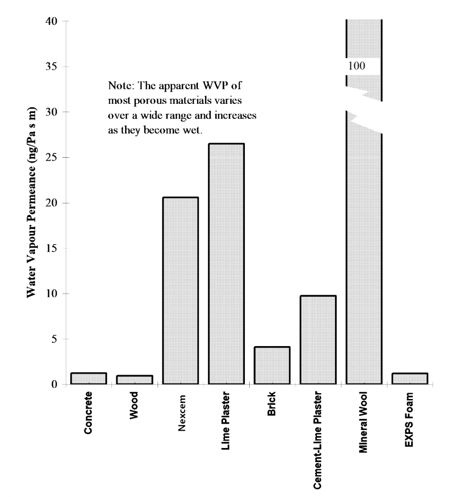
Figure 1: Water Vapour Permeance of Various Building Materials
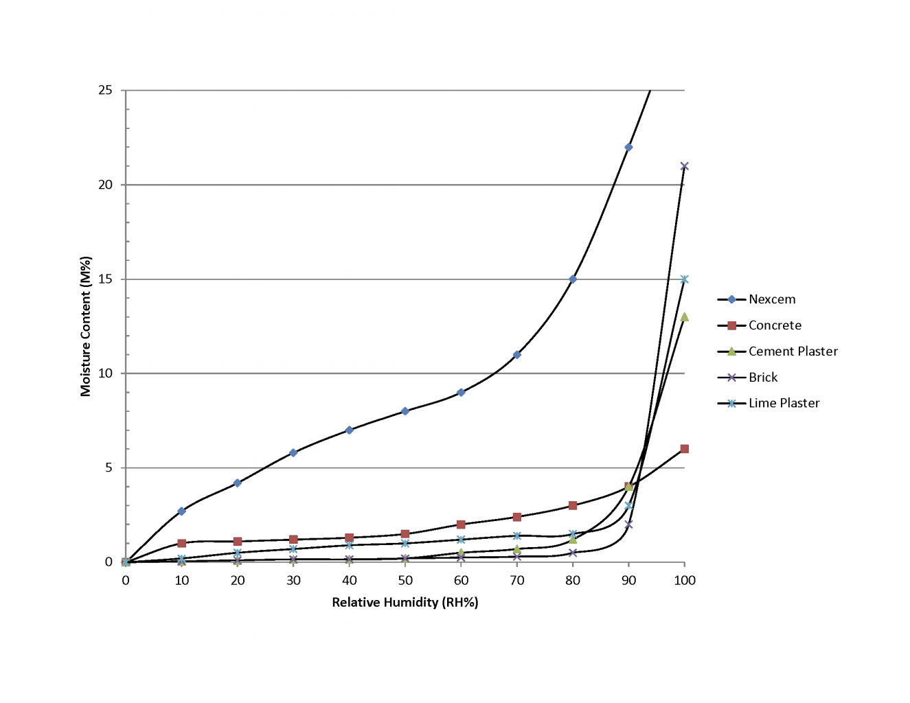
Figure 2: Sorption Isotherm for Various Building Materials (Larger version)
Dynamic Hygric Response
A recent multi-year study concluded that short-term RH peaks of a building’s air can support fungal growth, even though the average conditions are well below the threshold for fungal growth, e.g., 70 to 80% RH (Adan 1994). For example, the simple act of boiling water for cooking creates a significant short-term rise in humidity near the kitchen. After the interior RH has dropped, the fungi can continue to grow for some time using moisture stored within the fungi.
The speed with which a wall surface can absorb moisture is important for avoiding surface condensation and surface relative humidities required to support fungal growth. Materials with a combination of the properties of vapour permeability and high hygroscopicity allow that material to quickly moderate humidity variations by storing or releasing significant quantities of water vapour. A vapour tight finish on walls allows the surface relative humidity to climb to the level where fungal growth can be sustained.
If a material can quickly adsorb moisture from the air, this material will maintain the RH at its surface at a lower and more stable level while also moderating short-term interior air humidity variations. The dynamic hygric response of several wall systems was studied with the aid of computer modelling and field measurements. The results are presented below.
Modelling Hygric Response
Using a sophisticated computerised finite element package (developed by Kuenzel, 1997) the amount of moisture released into a room by several different wall systems was calculated. The program is one of the most advanced in the world (it considers different moisture diffusivities for suction and redistribution, surface diffusion, capillarity, vapour diffusion, etc.).
Each of the assemblies modelled comprised a 200 mm layer of material. Some of the walls were finished with lime plaster, others with gypsum drywall and various paints. Material properties were taken from manufacturerís data and various sources (ASHRAE 1997, IEA 1997). The simulation considered a wall and room initially at 30%RH followed by an instantaneous rise in room air moisture content to 80%RH. Over the period of a week the simulation calculated the water vapour balance every 15 minutes.
Figure 3 plots the moisture adsorption of four walls for the first 24 hours. All of the systems responded in a similar manner, but the speed of response differed considerably. The initial response was fast, followed by a slow exponentially decaying period. Because the shape of the response curves are similar, the results can be usefully summarized and wall systems approximately ranked: see Table 1.
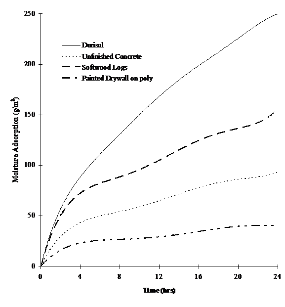
Figure 3: Calculated hygric response of four wall systems to a 50%RH change (Larger version)
Table 1 shows that there is a large difference between the behavior of some common wall systems. The plastered Nexcem insulated concrete form system and strawbale wall provide about 8 times more vapour control to the indoor environment than the walls used in a typical modern home, and 25 times that of a modern motel room with vinyl wall paper. While the above results do not attempt to exhaustively rate each assembly (the more complex discussions and calculations necessary for this are beyond the scope of this paper), it does provide a relative ranking which clearly shows the problems associated with the use of the most common modern building systems.
The simulation results also showed the clear superiority of lime-based plasters over pure cement-based plaster. The hygroscopic and highly vapour permeable nature of lime plaster provides a very fast response (i.e., several minutes) to changes in the vapour content of the interior air. Substrates like Nexcem, strawbales, and brick provide much more moisture storage, storage which participates at longer time scales (i.e., several hours). The worst possible finish is a high-grade vinyl wall, which not only off-gases VOCs but also returns vapour adsorption values of less than about 10.
[g/m2] | Rating Assembly Description |
| < 10 | Any system with vapour retarding paint (including oil based) or “high- quality ” vinyl wall paper |
| 40 | Painted gypsum drywall on poly on wood frame, primer + 2 coats latex |
| 90 | Concrete, unfinished |
| 110 | Modern extruded brick, unfinished |
| 150 | Softwood logs, unfinished |
| 240 | Strawbale wall with 1″ lime plaster |
| 250 | Nexcem Wall Form 20 System, finished with 12.5 mm lime plaster |
Table 1: Water vapour absorbed in 24 hours by walls exposed to a 50%RH change
Consider a room with exterior walls that cover 20 m2 of its 3 x 5 meter, 37.5 m3 volume. Air at 20 ºC and 50%RH contains about 8.7 g/m3. If 200 g of water (about 6.75 fluid ounces) were to be injected into the air, by human metabolism, cooking, etc., the moisture content of the air would rise by 200 g / 37.5 m3 = 5.3 g/m3 and the humidity of the air would rise to above 80%RH. If the source of vapour is cooking or a shower, the water would be quickly injected into the air, and the RH at the surface of any cool exterior wall (in this case any surface cooler than 16 ºC) would reach 100%. If the exterior walls of a room were able to absorb this moisture, i.e., 200 g / 20 m2 = 10 g/m2 of wall area, the RH within the room would be maintained, and the surface RH would remain below the threshold for fungal growth. This amount of moisture adsorption is easily and quickly (less than one hour) possible for walls rated over about 150 in Table 1; it is not possible for walls rated less than about 50. If all of the roomís walls were breathing walls, the response would be even faster and more powerful.
Outdoor air at 80%RH and 0 ºC contains about 3.9 g/m3. If the room in the previous example were ventilated at one air change per hour with outdoor air, approximately 37.5 m3 x (8.7 – 3.9) = 180 g of moisture would be removed by ventilation. Thus, ventilation is just as powerful a means of controlling indoor air moisture content as breathable walls. In buildings made with vapour tight walls, ventilation becomes the most important means of vapour control. Ventilation, however, cannot always guarantee moisture removal in the corners of rooms, behind furniture, etc. Ventilation is always necessary because it aids in the removal of other pollutants and delivers oxygen to a room faster than diffusion. Unfortunately, controlling ventilation requires mechanisms (electronics and fans) and/or proper occupant control.
Hygroscopic, “breathable” walls operate automatically, require no energy and cannot break down. Such walls can also react much more quickly than ventilation. Ventilation and breathing walls are likely best used as complementary techniques for ensuring IAQ.
Field Measurements of Hygric Response
Although computer modelling can be a powerful tool, field measurements are always the best and most reliable means of testing theory. A total of ten different wall types were part of the research program. Space limitations allow for the comparison of only two — the Durisol Insulated Concrete Form system and a well-built, highly insulated steel stud wall system, both clad with brick veneer. Simplified horizontal sections of the walls are shown in Figure 4.
Wall B clearly contains more thermal mass and a large amount of vapour storage. However, another major difference was the use of a vapour barrier. The Wall A used a sheet of 6 mil polyethylene (0.06 US perms, 3.4 ng/Pa/s/m2 ) behind the drywall finish. Wall B used an unpainted sheet of drywall only — unpainted drywall is very vapour permeable (over 20 US perms or 2000 ng/Pa/s/m2). To create a potentially dangerous situation, 51 mm of extruded polystyrene insulation (vapour resistant) was placed outside of Wall B, and the drywall was left unpainted to “trap” vapour in the wall. Vapour permeable plasters or recycled rockwool insulation is typically recommended outside of Durisol walls, or thicker, more highly insulated forms are specified.
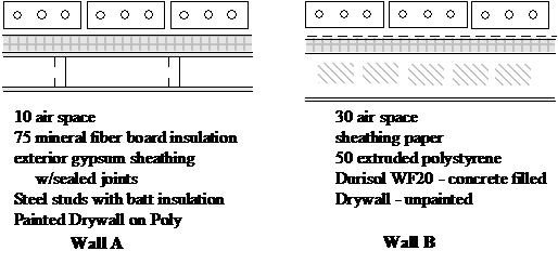
Figure 4: Horizontal section of test walls A and B (schematic)
Figures 5 and 6 plot the relative humidity measured in the Wall A and B respectively over the winter period (from 961031 to 970331. The maximum and the minimum 15 minute average values for each day have been plotted from the data collected at 5 minute intervals. The interior of the test house was carefully maintained at 21 ºC ±1 ºC and 50% ±5%RH over the entire period. This is a higher RH than most houses but is representative of many commercial building environments.
A comparison of the two plots clearly shows the humidity moderating effect within the Durisol material of Wall B. Over the entire heating period, the daily RH variation (i.e., maximum less minimum) was 15.3% for Wall A and only 2.6% for Wall B.
An inspection of the relative humidity measurements in Wall B also shows that they never approached levels at which condensation might occur, even though there was no vapour retarder on the warm side of the wall, and despite a relatively impermeable outer sheathing. This data was collected over a winter in which the outdoor temperature dropped below -20 ºC (-4 ºF) several times. In fact, Wall A with a polyethylene retarder exhibited far more chance of condensation than Wall B. If the drywall had been painted, the Durisol plastered, or the EXPS sheathing replaced with a more vapour permeable material, the RH in Wall B would have been even lower.

Figure 5: Maximum and minimum relative humidity in Wall A (Larger version)
Wall B also exhibited much higher summertime RHís because of vapour flow from the outdoors to the indoors. The polyethylene trapped this vapour within Wall A. These inward vapour drives have been found to be a problem in many walls, especially in climates similar to or warmer than South-western Ontario (Straube and Burnett 1995).
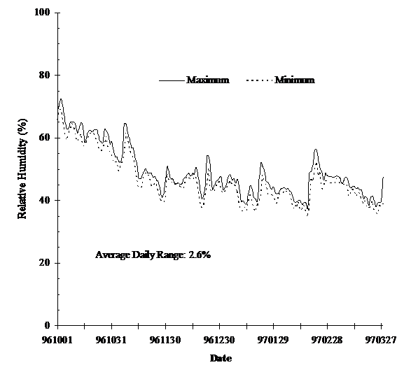
Figure 6: Maximum and minimum relative humidity in Wall B (Larger version)
Conclusions
The indoor air quality of a building directly impacts the health and productivity of its occupants. There are several design strategies that can be used to deliver good IAQ. Controlled ventilation, proper design, occupant behaviour, and the use of appropriate healthy building materials within a holistic design approach can provide good indoor air quality. As part of a complete IAQ design strategy, so-called breathing walls can moderate indoor humidity and practically eliminate the potential for fungal growth on building surfaces.
The properties of the Durisol cement-bonded wood fibre material, like strawbale, are ideal for use in breathing walls because of their combination of vapour permeable and hygroscopic properties.
The results from the field monitoring demonstrated both the humidity moderating effect and the fact the no polyethylene vapour barrier is required in such walls.
Downland the summary of this document – Indoor Air Quality (PDF)
References
Adan, O., On the Fungal Defacement of Interior Finishes, Ph.D Thesis, Eindhoven University of Technology, Eindhoven, Netherlands, 1994.
ASHRAE, 1997. 1997 ASHRAE Handbook – Fundamentals, Atlanta: American Society of Heating Refrigerating, and Air-Conditioning Engineers, Inc.
Baggs, S. and J., The Healthy House: the Gaian approach to creating a safe healthy and environmentally friendly home, Harper & Collins, Sydney, 1996.
Bower, J., Healthy House Building, The Healthy House Institute, Unionville, Indiana, 1993.
Fisk W. and Rosenfeld A., “Improved Productivity and Health from Better Indoor Environments”, Center for Building Science Newsletter, Lawrence-Berkeley Labs, Summer, 1997.
International Energy Agency. Report Annex 24, Task 1: Hygrothermal Properties of Building Materials. ed. M.K. Kumaran, 1997.
Krusche, P, Weig-Krusche, M., Althaus, D., Gabriel, I., Oekologisches Bauen, Bauverlag, Berlin, 1982.
Kuenzel, H., “Muessen Aussenwaende ëatmungsfaehigí sein?” wksb, Nov., 1980, pp. 1-4.
Kuenzel, H.M., WUFI V2.0 – Simultaneous Heat and Moisture Transport in Building Components, Fraunhofer Institute for Building Physics, August 1997.
Levon, B.-V., “Experimentbyggnade i Norden”, Swedish Council for Building Research, Report T5, 1986, pp. 158-160.
Marinelli, J. and Bierman-Lyle, P., Your Natural Home. Little, Brown, & Co., Boston, 1995, pp. 81-84.
Pearson, D., The Natural House Book, Simon & Schuster/Fireside, New York, 1989.
Roodman, D.M., and Lenssen, N., A. Building Revolution: How Ecology and Health Concerns are Transforming Construction. World Watch Institute, Washington, D.C., 1995.
Rousseau, D., Rea, W.J., Enwright, J. Your Home, Your Health, and Well-Being. Hartley & Marks, Vancouver, 1989.
Scanada Consultants, Mould in Finished Basements, Report for Canada Mortgage and Housing Corporation, Ottawa, 1995.
Significance of Fungi in Indoor Air: Report of a Working Group. Health & Welfare Canada, Ottawa, 1987.
Straube, J.F. Burnett, E.F.P.. In-Service Performance of Enclosure Walls. Volume 1: Summary Final Report. Building Engineering Research Report: University of Waterloo, 1997.
Straube, J.F., and Burnett, E.F.P., “Moisture Movement in Building Enclosure Wall Systems”, Proceedings of the Thermal Performance of Building Envelopes VI, Clearwater Beach Florida, December 4-7, 1995, pp. 177 – 188.
Taylor, B J, Webster, R., Imbabi, M.S., “The use of dynamic and diffusive insulation for combined heat recovery and ventilation in buildings”, Building Environmental Performance Analysis Club, Proceedings of Sustainable Building Conference, Feb 5-6, 1997, Abingdon, UK, pp. 168-174.
Timusk, J, “Design, Construction, and Performance of a Dynamic Wall House”, Presented at AIVC Conference, Sept 24, 1987, Ueberlingen, Germany.
Turpin, B. ” sdg” ASHRAE Summer Meeting, 28 June- 2 July, 1997.
van Vliet, J., Building Materials for the Environmentally Hypersensitive, Canada Mortgage and Housing Corporation, Ottawa, 1995.
Lacinski, P., “Breathing Wall”, The Last Straw – the journal of strawbale construction, Spring 1996.